Answers to Eight Common Questions about Pneumatic Conveying
While pneumatic conveying is a common method of transferring powders, granules, and other dry bulk materials, understanding this conveying technology can be a challenge. This article addresses pneumatic conveying questions frequently asked by people in dry bulk materials processing and handling plants.

What is a pneumatic conveying system?
A pneumatic conveying system transfers powders, granules, and other dry bulk materials through an enclosed pipeline. The motive force for this transfer comes from a combination of pressure differential and the flow of a gas, such as air or nitrogen. (For simplicity, we’ll call the gas “air” in this article.) The system’s basic elements include a motive air source (also called an air mover, such as a fan or blower), a feeder or similar material-introduction device, a conveying line, a termination vessel (such as an air- material receiver), and a dust collection system.
While some of the most common materials transferred by pneumatic conveying systems are flour, cement, sand, and plastic pellets, any of hundreds of chemicals, food products, and minerals can be pneumatically conveyed. These materials are usually fairly dry; materials in slurry or paste form typically aren’t suited to pneumatic conveying.
How does a pneumatic conveying system work?
Doing work requires energy. To turn a bolt, for instance, you need to provide energy in the form of torque. Such mechanical torque is usually expressed in foot-pounds, and both elements — feet and pounds — are needed to do the work. Energy is also required to move material through a pneumatic conveying system, but in this case, the energy is supplied by pressure differential (in pounds per square inch) and airflow (in cubic feet per minute).
In a pneumatic conveying system, the air pressure in the conveying line is changed by the system’s air mover, which generates pressure or vacuum. Where the air mover is located in the system determines whether it generates one or the other: When located at the system’s start, the air mover pushes air through the system and the system operates under pressure. When located at the system’s end, the air mover pulls air through the system and the system runs under vacuum. By controlling the pressure or vacuum and airflow inside the system, the system can successfully transfer materials.
What are the advantages of a pneumatic conveying system over a mechanical conveying system?
Let’s start by looking at mechanical conveying systems. A conventional mechanical conveying system runs in a straight line, with minimal directional changes, and each directional change typically requires its own motor and drive. The mechanical conveying system may be open rather than enclosed, potentially generating dust. It also has a relatively large number of moving parts, which usually require frequent maintenance. The system also tends to take up a lot of valuable real estate in a plant.
On the other hand, a pneumatic conveying system uses a simple, small-diameter pipeline to transfer material. The pipeline can be arranged with bends to fit around existing equipment, giving the system more layout flexibility, and the system also has a relatively small footprint. The system is totally enclosed and typically has few moving parts.
What are the disadvantages of a pneumatic conveying system in comparison to a mechanical conveying system?
A pneumatic conveying system typically requires far more horsepower to operate than an equivalently sized mechanical conveying system. The reason is that changing the air pressure to achieve pneumatic conveying consumes a large amount of power and is inherently less efficient than a mechanical conveying system’s mechanical transfer. In fact, in applications with the same transfer rate over the same conveying distance, a pneumatic conveying system can require 10 times the horsepower of a mechanical conveying system. A pneumatic conveying system also requires a larger dust collection system than a mechanical conveying system. This is because the pneumatic system has to separate the conveyed material from the conveying air at the system’s end.
Some materials have characteristics that make them difficult to convey in a pneumatic system. Examples are a material with a large particle size and high bulk density, such as gravel or rocks, and an extremely sticky material, such as titanium dioxide, which tends to build a coating on any material-contact surface. In a pneumatic conveying system, such buildup often leads to total pipeline blockage. These difficult materials can be easier to transfer in a mechanical conveying system that’s been carefully chosen to handle them.
What are the types of pneumatic conveying systems?
Pneumatic conveying systems are classified by their operating principle into two types: dilute phase and dense phase. Either can run under pressure or vacuum.
Dilute Phase
Dilute phase (also called stream-flow) pneumatic conveying is best compared to what happens in a parking lot on a blustery day. While walking to your car after work, you’re blasted with dust and dirt that’s been picked up off the ground by fast-moving wind. The faster the wind, the more material hits you. As the wind speed picks up, larger dirt particles also become entrained in the wind. Picture the debris carried by a tornado or hurricane: These storms are pneumatically transferring enormous “particles” in dilute phase. Just like the wind picks up the dust, the dilute-phase conveying system relies on the airstream’s velocity to pick up and entrain each particle, keeping the particles in suspension throughout the conveying line.
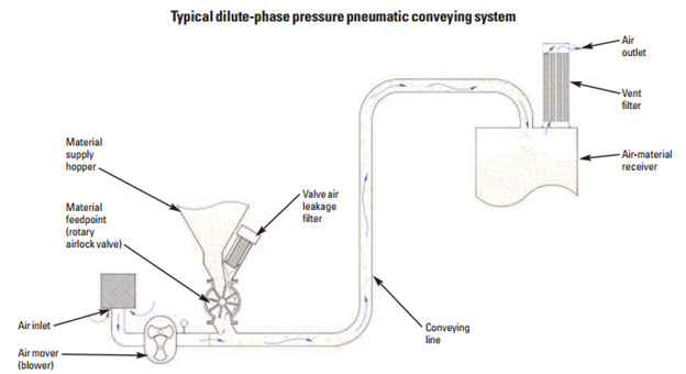
A typical dilute phase pneumatic conveying system is shown in Figure 1. They pick up velocity at the system’s start (that is, the airstream velocity at which material is picked up and entrained at the material feed point) is generally considered the system’s most critical area, because the air is at its lowest speed in the entire system at this point. Because the material is dropping from a static state into the airstream below it, the material must immediately become entrained. The air speed required to pick up the material depends on each particle’s size and density, but can range from 3,000 to 8,000 fpm. The air mover must also be able to overcome the flow resistance caused by the frictional loss of the air and material against the conveying line’s inside wall.
A simple way to think of a dilute phase conveying system is that it operates at a relatively high velocity at a relatively low pressure differential. To design a dilute phase pneumatic conveying system with the air volume to convey your material, you must use mass calculations (that is, pounds of material per pound of air) while considering your installation location’s ambient air temperature, humidity, and altitude. Then to achieve the proper mixture of air and material in the system, you must meter the material into it at a controlled rate.

Dense Phase
Dense phase pneumatic conveying is also best described with an analogy: It’s similar to what happens in making sausage, when you use high pressure to force ground meat into a casing. An ideal dense phase conveying system would extrude material with enough pressure to transfer it in one long, continuous piece through the pipeline’s entire length, just like a continuous length of ground meat inside a sausage casing. But with dry bulk materials like powders and granules, this usually isn’t possible because of the material’s high frictional resistance against the conveying line’s inside wall. Instead, air and material flows through the line in any of several patterns (including various forms of two-phase flow and slug flow).
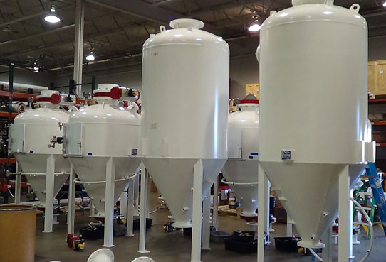
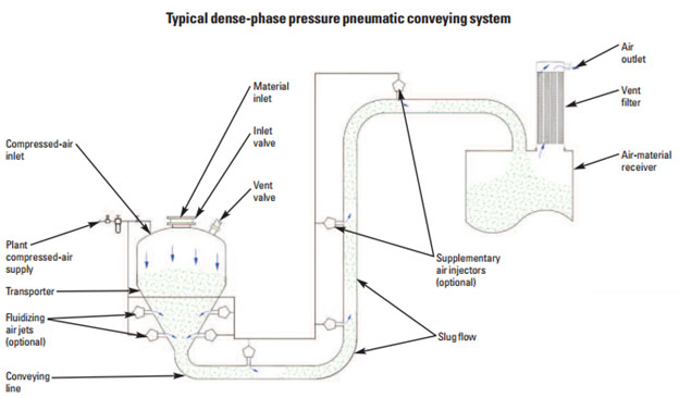
While various dense phase conveying system types are available, all use a relatively high pressure differential with a relatively low air velocity. The most common dense phase system type, as shown in Figure 2, provides batch transfer using a transporter (also called a blow tank or pressure tank). In this system, material from a storage vessel is loaded by gravity into the transporter. After the transporter is full, its material inlet valve and vent valve are closed and compressed air is metered into the transporter. The compressed air extrudes the material from the transporter into the conveying line and to the destination. Once the transporter and conveying line are empty, the compressed air is turned off and the transporter is reloaded. This cycle continues until all the material required for the process has been transferred.

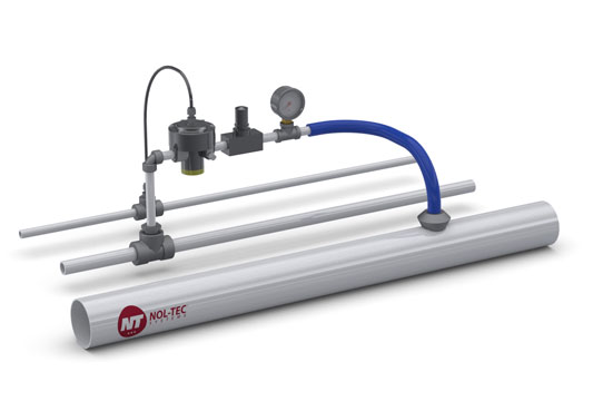
Some dense phase systems have supplemental air injectors (also called air boosters or air assists) located along the conveying line (Figure 2). Shown in detail in Figure 3, an air injector works by injecting compressed air (or another gas, such as nitrogen, to match the conveying gas) into the conveying line. The added air can clear any plugs caused by low air volume or pressure, eliminating the chore of dismantling the line to remove plugs. Using the injectors reduces the system’s air volume safety factor by reducing the air volume required for reliably conveying the material. (An air volume safety factor is typically built into a pneumatic conveying system’s design to ensure that the system has slightly more air volume than the application requires; however, while this extra air volume helps the system reliably convey material without plugging, it also increases the system’s energy consumption.)
Air injectors along the conveying line can also be used to gently restart flow when material is left in the line after the conveying cycle. This is a particular advantage for a system handling an abrasive or friable material or a material blend. When the system is restarted without supplementary air, the higher-speed material flow can cause an abrasive material to produce excessive and premature wear on the conveying line and other material-contact components. This higher-speed flow can also damage a friable material, resulting in unacceptably high amounts of particle attrition. It can also deblend a mixture of materials with different particle sizes and bulk densities. Using supplementary air in the line can not only prevent wear, attrition, and deblending problems when a power outage or other event abruptly shuts down the conveying system when it’s full of material, but can provide more system design flexibility for an application where you want to intentionally leave material in the line between cycles.
Air injectors must be designed as fail-safe check valves to prevent the conveyed material from intruding into the injectors’ compressed-air supply. Such intrusion can occur when material slugs (also called pistons) form inside the dense-phase conveying line (Figure 2); because of the slugs’ changing velocity in the line, usually before line bends, the air in the pockets between the slugs can become pressurized to a level higher than that of the compressed air injected into the line. If this overpressure condition occurs at an air-injection point and the air injector doesn’t have a check valve, some particles can enter the compressed-air supply.

Is there a standard way of categorizing when a pneumatic conveying system is operating in dilute phase or dense phase?
Unfortunately, there’s no industry standard for measuring these operating phases. So just because a pneumatic conveying system has a rotary airlock valve, it’s not necessarily operating in dilute phase, and just because a system has a transporter, it’s not necessarily operating in dense phase.
However, you can use these rules of thumb for determining a pneumatic conveying systems operating phase:
- Most dilute phase pressure systems operate below 15 psi (typically between 4 and 8 psi), while most dense-phase pressure systems run above 15 psi.
- Most dilute phase vacuum systems operate below 12 inches mercury (typically between 8 and 12 inches mercury), while most dense-phase vacuum systems run above 12 inches mercury (typically between 12 and 14 inches mercury).
- Depending on the conveyed material, most pressure and vacuum dilute phase systems have an air velocity between 3,500 and 9,000 fpm and most pressure and vacuum dense-phase systems have a 3,000-fpm or lower air velocity.
- In a dilute phase system, the material velocity is nearly the same as the air velocity. In a dense-phase system, especially one with slug flow, the average material velocity is much slower than the air velocity. In either system, the material can’t move faster than the air.
One caution: When you’re talking to a dense phase system supplier about selecting a new system, make sure that the material velocity numbers the supplier is using are clearly defined. Some suppliers use air velocity and material velocity numbers interchangeably. Make sure you know what numbers the supplier is talking about before you accept the supplier’s material velocity claims.
How do I select a pneumatic conveying system for my application?
Major Factors to Consider
The first thing to address when selecting a dilute or dense phase pneumatic conveying system is your material’s characteristics. These include the material’s particle size and shape, bulk density, moisture content, abrasiveness, friability, cohesiveness, hygroscopicity, static charge, explosivity, toxicity, melt point, and many others.
Next, consider how the system will fit into your location and plant environment. How will the system’s planned line routing and length fit into your installation area? Are there any physical constraints in the area, such as other equipment or spots with low headroom? What will it take to fit the system into your available area within these constraints? And how can the system be configured to provide easy maintenance access to system components?
Another major factor to consider is what material transfer rate the system must achieve to meet your application requirements.
Making a Choice
Assuming that your material can be pneumatically conveyed (that is, it doesn’t have a large particle size and high bulk density and it isn’t extremely sticky), and without considering any other factors at this point, start by considering the conveying system with the lowest initial investment cost: dilute phase.
Whether the dilute phase system should operate under pressure or vacuum in your application depends on two main factors:
- Whether air leaking into or out of the system will have a negative effect: For instance, air leaking out of a pressure system that conveys a toxic or explosive material can create hazardous conditions in your plant. In this case, a vacuum system would be a safer choice.
- Whether your material packs tightly (like wood shavings), is cohesive and tends to build up on surfaces (like titanium dioxide), or is fibrous (like some grain hulls): For materials like these, a vacuum system may be the better choice. This is because the vacuum in the conveying line tends to pull the particles apart during conveying rather than push them together or into the line walls as pressure conveying does.
Some factors may make a dense phase conveying system better suited to your material. The dilute phase system relies mainly on providing a high enough air velocity to keep material entrained in the airstream. This relatively high velocity can damage a friable material, resulting in unacceptably high amounts of particle attrition. It can also deblend a mixture of materials with different particle sizes and bulk densities. In both cases, the gentler conveying in a dense phase system — which relies more on a high pressure differential than a high air velocity — is often a better option. The dilute phase system’s high velocity can also be a problem for handling an abrasive material, which can quickly wear the conveying line and other components, making a dense-phase system the clear choice in this case.
Also, consider a dense phase conveying system when your system will include long conveying line runs. A dense phase system typically requires a smaller line diameter than a comparably-sized dilute phase system. This means that the dense-phase system not only requires less air volume but, in a long system, the smaller-diameter line sections are much lighter, making their installation and replacement easier. The dense phase system’s smaller and lighter elbows and similar components provide the same advantages. Choosing pressure or vacuum operation for your dense phase conveying system depends on the same factors as for a dilute phase system: whether air leaking into or out of the system will have a negative effect and whether your material packs tightly, is extremely cohesive and tends to build up on surfaces, or is fibrous.
How can pilot-plant testing help me design a pneumatic conveying system?
Once you’ve decided on a dilute or dense phase pneumatic conveying system and determined whether it will operate under pressure or vacuum, have the system supplier run pilot-plant tests of the proposed system in the supplier’s test facility. The supplier should conduct the tests with the same material the installed system will handle in your plant and simulate your field conditions as closely as possible. This includes configuring the pilot- plant system, if possible, with the same conveying line routing, length, and number of bends that the installed system will have and running the tests under your plant’s ambient air temperature and humidity conditions.
Before the supplier runs the tests, you should define several test criteria. Basic criteria include whether the proposed system conveys your material, at what rate it conveys the material, and how much air the system consumes. You also need to define criteria specific to your application. If, for instance, you’re conveying a friable material and are concerned about material attrition, you need to define how much attrition is acceptable and then accurately verify how much attrition occurs during the tests. The supplier will use the pilot-plant test results to size the conveying system that’s installed in your plant. Make sure that you understand exactly how the supplier will use the test results to size your installed system and, in particular, how the supplier will use the data to calculate the installed system’s material conveying rate and air consumption.
Key Takeaways
Pneumatic conveying is classified by two main system types, offers many advantages compared to mechanical conveying, and is suitable for many different types of applications.
- A pneumatic conveying system transfers powders, granules, and other dry bulk materials through an enclosed pipeline using a motive force, typically air.
- A pneumatic conveying system is classified by two main types, dense and dilute.
- A proposed pneumatic conveying system can be tested prior to purchase to ensure it will operate as expected once installed at a clients’ facility.
How can we help?
Maybe you need a new system, an upgrade to an existing system, or a retrofit. Regardless of size, industry, or material, we are here to help you get your project and product moving.
Get in touch